What is sodium iron phosphate and its grinding method? Sodium-ion batteries are moving from research labs into mass production – and the cathode material is the key battleground. Among the leading candidates, Composite Sodium Iron Phosphate, formula Na₄Fe₃(PO₄)₂P₂O₇, abbreviated as NFPP, has emerged as one of the most commercially promising polyanionic cathode materials.
It offers a three-dimensional framework structure, strong thermal stability, a theoretical specific capacity of around 129 mAh/g, and it is made from iron and phosphate, two of the cheapest and most abundant elements on Earth. For a battery technology competing on cost, that matters.
But raw NFPP material alone is not enough. The particle size, purity, and surface chemistry of the powder directly determine how well the battery performs. This article explains what NFPP is, how its crystal structures affect electrochemical performance, and which grinding methods are used and why in industrial production.
What Is Sodium Iron Phosphate (NFPP)?
Sodium iron phosphate (NaFePO₄) is a family of inorganic compounds that share a common feature: a framework of sodium, iron, phosphorus, and oxygen arranged in structures that allow sodium ions to move in and out during charging and discharging.
The name covers several distinct crystal structures, not a single compound. Each structure has different electrochemical characteristics, and understanding these differences is important for selecting the right synthesis and processing approach.
The Four Main Crystal Structures
1. Olivine NaFePO₄
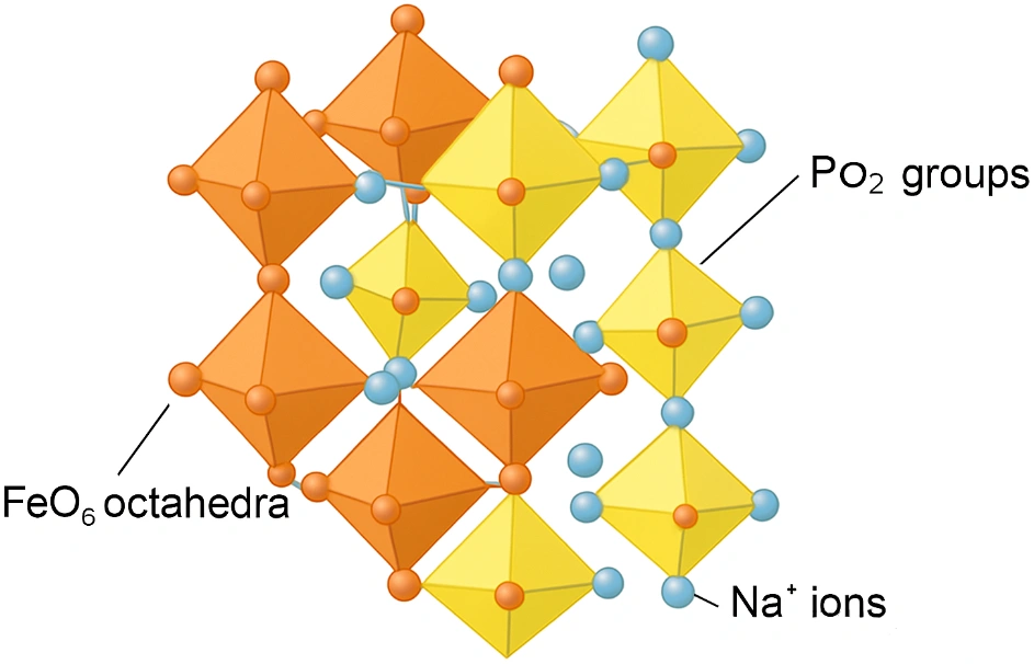
The most studied sodium iron phosphate structure. It has an orthorhombic or triclinic crystal arrangement with PO₄ tetrahedra and FeO₆ octahedra forming a three-dimensional framework. Sodium ions diffuse along one-dimensional channels within this framework.
The structure is closely related to lithium iron phosphate (LiFePO₄) – the proven lithium battery cathode – with sodium substituted for lithium. This structural similarity gives olivine NaFePO₄ excellent thermal stability and inherent safety, the same properties that make LFP popular. The trade-off is lower electronic conductivity, which limits rate performance unless addressed through carbon coating and particle size control.
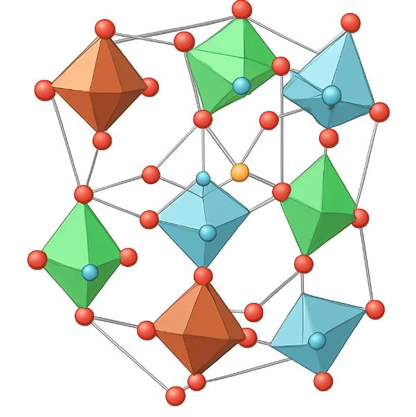
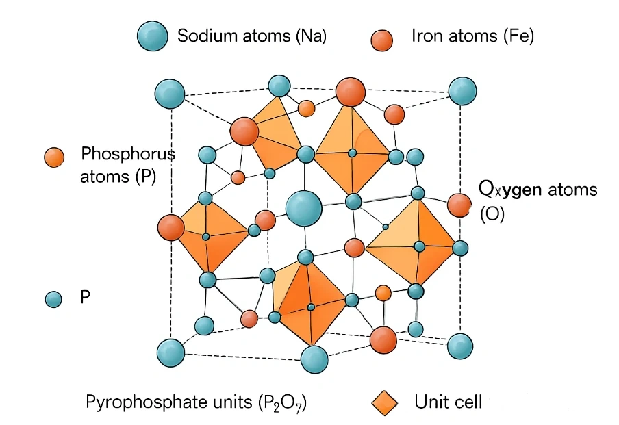
2. Mixed Phosphate Na₄Fe₃(PO₄)₂P₂O₇ (NFPP)
This is the compound that has attracted the most commercial attention and is the primary focus of this article. NFPP contains both phosphate (PO₄) and pyrophosphate (P₂O₇) units in the same structure, which creates a unique combination of properties: high energy density, long cycle life, and low material cost.
Its three-dimensional sodium-ion diffusion pathways – unlike the one-dimensional channels in olivine – give it inherently better rate capability. This makes NFPP a strong candidate for applications that need both high energy density and the ability to charge and discharge quickly.
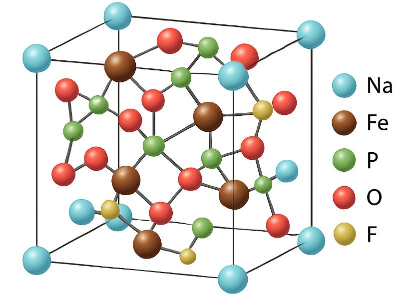
3. Fluorophosphate Na₂FePO₄F
Fluorophosphate sodium iron phosphate introduces fluorine ions into the structure, which raises the operating voltage and reduces the volume change during sodium insertion and extraction. Lower volume strain means better long-term cycle stability. Na₂FePO₄F operates in an orthorhombic structure and is of particular interest for applications where cycle life is the primary design constraint.
4. Amorphous FePO₄
In its non-crystalline form, iron phosphate follows a different electrochemical pathway. During sodiation, amorphous FePO₄ converts partly to amorphous sodium iron phosphate and partly to crystalline NaFePO₄. This conversion mechanism offers different capacity and rate characteristics from the crystalline structures above, and is the subject of active research for applications where conventional crystalline materials fall short.
| Structure | Voltage vs Na+/Na | Theoretical Capacity | Key Advantage |
| Olivine NaFePO₄ | ~2.9 V | 154 mAh/g | Thermal stability, safety |
| NFPP Na₄Fe₃(PO₄)₂P₂O₇ | ~3.2 V | 129 mAh/g | 3D diffusion, rate capability |
| Fluorophosphate Na₂FePO₄F | ~3.5 V | ~124 mAh/g | Low volume strain, long cycle life |
| Amorphous FePO₄ | Varies | Varies | Conversion mechanism, research stage |
Why Processing Matters So Much for NFPP
All sodium iron phosphate structures share a common limitation: low electronic conductivity and relatively slow sodium-ion diffusion kinetics. Left unaddressed, these properties limit rate performance and cause capacity fade over repeated cycles.
The solution to both problems runs through the grinding process. Smaller particles shorten the sodium-ion diffusion distance – the distance ions must travel through the solid material. A uniform particle size distribution ensures the entire electrode responds consistently to charge and discharge. And precise particle size control determines how well a carbon coating can be applied uniformly to the active material surface.
This is why grinding is not a secondary processing step for NFPP – it is one of the primary determinants of battery performance.
The Two Grinding Methods Used in NFPP Production
NFPP is produced primarily by solid-phase synthesis or spray drying followed by high-temperature sintering. Grinding is used at two distinct stages: mixing precursors before sintering, and deagglomerating and sizing the sintered product afterwards. Different methods are used at each stage, and the choice of method has a direct impact on the final electrochemical performance.
Method 1: High-Speed Mixer – Precursor Preparation
Before sintering, the raw materials – iron source, phosphorus source, sodium source, and carbon source such as glucose or carbon black – must be uniformly mixed at the microscopic level. High-speed mixers do this job using shear forces generated by a high-speed rotor.
Uniform distribution at this stage is foundational. If the precursors are not thoroughly mixed, the sintering reaction will be uneven, producing batches with inconsistent phase composition and variable electrochemical properties. The high-speed mixer breaks up initial agglomerates and achieves the intimate contact between particles that uniform sintering requires.
| Key operating pointDo not over-mix: Excessive mixing time or intensity at this stage can introduce impurities from equipment wear or cause localised overheating that triggers premature reactions. The goal is thorough mixing, not size reduction. |
Method 2: Jet Milling – Post-Sintering Deagglomeration and Sizing
After sintering, NFPP forms hard agglomerates that must be broken down before the material can be used in electrode slurries. Jet milling is the preferred method for this stage in high-purity production, and the reasons come directly from NFPP’s material requirements.
A jet mill accelerates particles using high-pressure gas – air or nitrogen – and causes them to collide with each other at high velocity. There are no grinding media and no rotating metal surfaces in contact with the product. Size reduction happens through particle-on-particle impact only.
- No contamination: NFPP is highly sensitive to metallic impurities, particularly magnetic metals like iron, nickel, and chromium. Even trace contamination from grinding media causes self-discharge and accelerated capacity fade. Jet milling eliminates this risk entirely – there is nothing to wear and contaminate the product.
- Precise particle size control: a dynamic classifier integrated with the jet mill controls the cut point. D50 can be held consistently in the 1-3 micron range with a narrow distribution – the range that optimises sodium-ion diffusion kinetics without creating excessive surface area that consumes electrolyte.
- Morphology preservation: because grinding is autogenous (particle-on-particle), jet milling applies less destructive force to individual particles than media milling. This helps preserve the secondary morphology – the structure of aggregated primary particles – that contributes to electrode packing density and rate performance.
One practical note: jet milling has high specific energy consumption, and very hard sintered NFPP blocks may require a preliminary jaw crushing or coarse grinding step before the material is suitable for jet mill feed. Pre-crushing to below 2-3 mm feed size is standard practice before jet milling sintered battery cathode materials.
Choosing the Right Grinding Method for Your NFPP Process
The three methods are not mutually exclusive. In a typical production line, all three may be used in sequence. The table below summarises when each method is applied and what it delivers:
| Method | Stage | Output PSD | Primary Purpose |
| High-speed mixer | Pre-sintering (precursor prep) | Not the goal – uniform mixing is | Achieve homogeneous precursor distribution |
| Jet mill | Post-sintering (dry) | D50 1-3 um, narrow span | Deagglomerate, size, zero contamination |
| Bead mill (sand mill) | Wet synthesis or slurry processing | Submicron to nano | Nano-dispersion, in-situ carbon coating |
| Need Help Processing NFPP or Other Battery Materials? At EPIC Powder Machinery, we supply jet mills configured for battery material production. Whether you are developing a new NFPP formulation or scaling up an existing process, our team can advise on the right equipment for your particle size targets, purity requirements, and production volume.Lab-scale trials are available before full production commitment. Request a Free Consultation: www.jet-mills.com/contact-us Explore Our Battery Material Grinding Systems: www.jet-mills.com |
Frequently Asked Questions
What makes NFPP (Na4Fe3(PO4)2P2O7) different from other sodium iron phosphate compounds?
NFPP contains both phosphate (PO4) and pyrophosphate (P2O7) units in its crystal structure, which creates three-dimensional sodium-ion diffusion pathways. Most other sodium iron phosphate structures – such as olivine NaFePO4 – have one-dimensional diffusion channels, which limits rate performance. The 3D pathways in NFPP allow faster sodium-ion movement, which improves rate capability and makes the material better suited to applications that require rapid charging. NFPP also uses only iron and phosphate – no cobalt, nickel, or manganese – which keeps raw material costs low and supply chains simple.
Why is jet milling preferred over ball milling for post-sintering NFPP processing?
NFPP is extremely sensitive to metallic contamination. Even traces of iron, nickel, or chromium from grinding media cause self-discharge and accelerate capacity fade – problems that appear in cycle life testing and reduce the commercial value of the material. Ball mills use steel or zirconia media that wear over time and introduce these contaminants. Jet mills have no grinding media and no metal surfaces in contact with the product: size reduction happens through particle-on-particle impact driven by compressed gas. For high-purity NFPP production, this zero-contamination characteristic is the deciding factor.
What particle size should NFPP be ground to for battery applications?
For most sodium-ion battery cathode applications, a D50 of 1-3 microns with a narrow particle size distribution is the standard target for jet-milled NFPP. At this size, the sodium-ion diffusion distance within each particle is short enough to support good rate performance, while the surface area is controlled enough to avoid excessive electrolyte consumption. The optimal particle size depends on your specific electrode design, binder system, and target C-rate.
Can NFPP be processed with the same equipment used for lithium iron phosphate (LFP)?
In many cases, yes – the processing requirements of NFPP and LFP are similar enough that the same equipment platforms can be used. Both materials require contamination-free dry grinding (jet milling), precise particle size control in the 1-5 micron range, and carbon coating to address low electronic conductivity. The main differences are in sintering conditions and the sensitivity of the specific crystal phases involved.
Epic Powder
Epic Powder, 20+ years of work experience in the ultrafine powder industry. Actively promote the future development of ultra-fine powder, focusing on crushing, grinding, classifying and modification process of ultra-fine powder. Contact us for a free consultation and customized solutions! Epic Powder—Your Trusted Powder Processing Expert!

“Thanks for reading. I hope my article helps. Please leave a comment down below. You may also contact EPIC Powder online customer representative Zelda for any further inquiries.”
—Jason Wang, Engineer