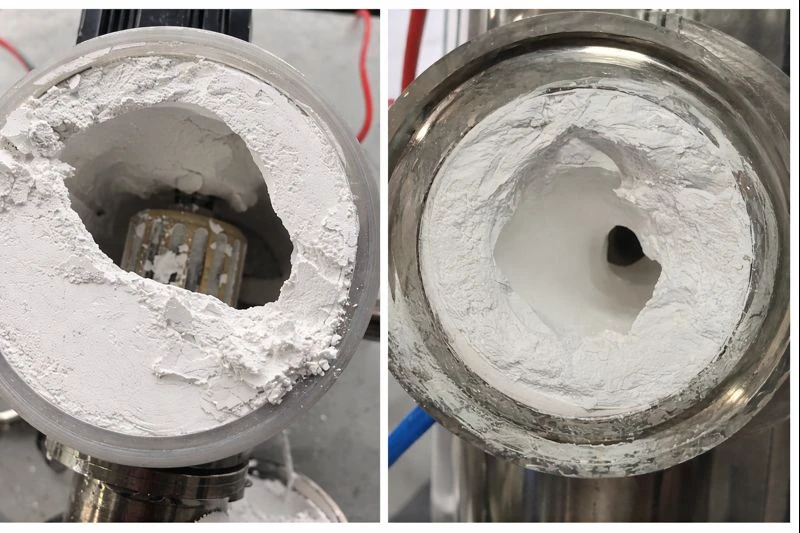
Have you encountered significant material buildup on the inner walls when grinding barium titanate using a jet mill? This article introduces how to effectively address wall adhesion issues during the grinding process.
Step 1: Understand the Root Cause of Buildup
Fundamentally, wall adhesion stems from strong interparticle and particle-wall forces, including van der Waals forces, electrostatic attraction, capillary forces, and adhesion due to plastic deformation. There are five key contributing factors:
Excessive Moisture Content: Even trace moisture (<0.5%) can significantly increase particle adhesion.
Overly Fine Particle Size (<10 μm): High specific surface area and surface energy promote agglomeration.
Low Softening Point or Thermal Sensitivity: Grinding heat can cause localized melting or softening.
Electrostatic Buildup: Friction in dry environments generates static charge, causing particles to adhere to metal surfaces.
Lack of Grinding Aids: Absence of anti-adhesion, dispersing, or lubricating additives.
Step 2: Pinpoint the Problem
We must distinguish whether the adhesion is due to physical adsorption (van der Waals, electrostatic), chemical adhesion (surface functional groups), or thermal softening/melting. Ask these three diagnostic questions:
What is the material?
Is it inorganic (e.g., calcium carbonate, alumina), organic (e.g., resin, wax, API), or a composite? Does it contain sugars, polyphenols, oils, fats, or low-melting-point components?
| Question to Ask | Specific Scenario | Dominant Wall-Sticking Mechanism | Typical Manifestation/Signal | Keywords/Basis |
| What is the material? | Inorganic | High specific surface area + electrostatic adsorption Trace moisture bridging (capillary forces) | Powder appears dry but is “fluffy and difficult to flow” Cake formation at discharge | D50 < 10 μm Moisture content > 0.1% High resistivity |
| Organic | Thermal softening/melting (T ≥ Tg/Tm) Molecular chain viscoelastic entanglement | Wall sticking intensifies after 30 mins of operation Oily sheen or translucent film Residue inside cavity | DSC shows Tg/Tm < 80°C Discharge temperature close to Tg Current increases over time | |
| Composite System | Multi-component synergistic adhesion (hard + soft + oily) Moisture absorption – heat release – adhesion positive feedback loop | Initially normal, rapidly worsens later Residue appears yellowish, rubbery stable lumps Slight burnt odor | Color change, whitish turbidity, PEG, low melting point components Hygroscopic (RH sensitive) Thermal analysis (TGA) shows weight loss at low temperature |
Where is it sticking?
Mill chamber walls? Agitator shaft? Discharge outlet? Screen/gap area? Is it a uniform film or localized buildup?
| Question to Ask | Specific Scenario | Dominant Wall-Sticking Mechanism | Typical Manifestation/Signal | Key Judgment Basis |
| Adhesion Location | Cylinder inner wall | Centrifugal force throwing powder + no scraping Condensation effect on wall surface Concentrated electrostatic field adsorption | Inner wall uniformly coated with powder Forms a rubbery/hard film after shutdown | Uniform distribution No obvious accumulation points |
| Agitator shaft/blade root | Flow dead zone settling Shaft-cavity gap compaction Local frictional heating and softening | Annular hard lump at shaft root Agitator torque fluctuates | Localized, symmetrical accumulation Gap < 2 mm | |
| Discharge port/screen/gap | Sudden flow velocity drop + increased residence time T Screen bridging clogging Shear heating + compaction in gap = sintering | Discharge intermittent/jams Screen partially blocked Current spikes | Wall sticking concentrated near outletObserved during shutdown inspection |
When does it start sticking?
Is it immediately upon startup? After a certain runtime (e.g., 30 minutes)? Is it accompanied by temperature rise, current fluctuation, or slowed discharge?
| Question to Ask | Specific Scenario | Dominant Agglomeration Mechanism | Typical Manifestation/Signal | Key Judgment Basis |
| Occurrence Timing | Occurs immediately upon startup | Initial moisture/content of raw material Equipment preheating or residue from previous batch Initial static electricity burst | Severe caking from the first batch Poor powder flowability (angle of repose > 50°) | Immediate occurrence Independent of runtime |
| Appears 20-60 minutes after operation | Temperature rise approaches Tg/Tm Internal moisture migrates to surface due to heat Depletion of volatile additives | Current first drops (fineness) then rises (agglomeration) Discharge temperature continuously rises Caking occurs intermittently/worsens over time | Delayed appearance Strongly correlated with temperature rise | |
| Accompanied by temperature rise, current fluctuation, slowed discharge | System out of control Cake layer causes uneven load Loss of flowability (Hausner ratio > 1.4) | Host power fluctuates violently Discharge rate drops sharply Local overheating (IR temperature measurement) | Multiple parameters abnormal simultaneously System instability signal |
Step 3: Root Cause Analysis
We recommend the “4M1E” method for systematic troubleshooting: Material, Machine, Method, Medium (grinding media), and Environment. While detailed, this is the most reliable approach when direct identification is difficult, ensuring no potential cause is overlooked.
| Dimension | Possible Factors | Inspection Points |
|---|---|---|
| Material | High moisture content, fine particle size, large specific surface area, low softening point, strong static electricity | Measure moisture (Karl Fischer), DSC for melting point/Tg, Zeta potential or resistivity |
| Machine | Rough inner wall, no wall-scraping structure, insufficient cooling, medium wear | Check lining material, agitator type, whether jacket uses cooling medium |
| Method | Excessive rotational speed, improper fill rate, prolonged continuous operation | Record power curve, temperature rise rate, change in discharged particle size |
| Grinding Medium | Size mismatch, material prone to adsorption, surface contamination | Check if media forms clumps, needs cleaning or replacement |
| Environment | High humidity, static accumulation, lack of inert atmosphere | Monitor workshop RH, equipment grounding resistance, whether inert gas protection is used (from Academy of Sciences Research Institute) |
Step 4: Implement Solutions from the Easiest to Most In-depth
Prioritize actions based on cost, effectiveness, and feasibility. Here is a tiered strategy:
Quick Interventions
Dry the feedstock immediately if moisture >0.2%.
Add trace aids (e.g., 0.2% hydrophobic fumed silica or stearate).
Reduce feed rate to avoid localized overheating.
Check and ensure proper equipment grounding to dissipate static.
Process Optimization
Adjust rotation speed and fill ratio to find the “efficient but not hot” operating window.
Introduce intermittent operation with air/water cooling to keep the chamber temperature rise < (Material Tg – 20°C).
Switch to an inert atmosphere (e.g., N₂) to suppress oxidation, remove moisture, and discharge static.
Equipment & Formulation Upgrades
Replace internal linings with PTFE, zirconia, or polymer wear-resistant coatings.
Install wall-scraping agitators (e.g., anchor-type rotors with flexible blades).
Integrate pulse reverse blowing or bottom fluidizing air to actively remove wall deposits.
Develop specialized grinding aid formulations (e.g., containing silicone-based anti-adhesion agents).
Process Redesign
Evaluate wet grinding feasibility. If suitable, wet milling + spray drying may be more economical.
Pre-pelletize before grinding to form fine powder into micro-spheres, reducing initial stickiness.
Step 5: Verification and Iteration
Closed-loop verification is essential after any adjustment.
Short-term Metrics: Is buildup reduced? Is discharge smooth? Is current stable?
Mid-term Metrics: Are product D50, specific surface area, and flowability (Hausner ratio) on target?
Long-term Metrics: Is the equipment maintenance cycle extended? Is batch consistency improved?
We recommend keeping a grinding process log to record feed moisture, ambient temperature/humidity, main motor current, discharge temperature, aid type/dosage, and buildup scores to enable data-driven optimization.
Conclusion
In powder engineering, wall adhesion often manifests as a drastic change in the physicochemical properties of materials pushed to their grinding limits. It signals that the material may be approaching its technical processing boundary.
This challenge prompts us to either re-evaluate product design requirements (e.g., is D97 < 5μm truly necessary?) or consider altering the powder’s surface state (via coating or modification) rather than relentlessly pursuing finer particle size alone.
Epic Powder
Epic Powder is specialized in fine powder processing technology for mineral industry, chemical industry, food industry, pharama industry, etc. Our team has more than 20 years experience in various powders processing. We are a professional supplier of powder processing projects, especially powder milling, powder classifying, powder dispersing, powder classifying, powder surface treatment and waste recycling. We supply consultancy, testing, project design, machines, commissioning and training.

“Thanks for reading. I hope my article helps. Please leave a comment down below. You may also contact EPIC Powder online customer representative Zelda for any further inquiries.”
— Jason Wang, Senior Engineer