Jet milling is the standard choice for fine grinding of lithium battery cathode materials — and for good reason. The absence of grinding media contact means no metal wear particles in the product. The inert gas atmosphere means no oxidation or moisture exposure during processing. And the integrated dynamic classifier means you can target a specific D50 and D97 with a precision that ball milling or impact milling cannot match.
But jet milling is not a single technology. Spiral jet mills, fluidised bed jet mills, and opposed-jet mills all operate on the same basic principle. High-velocity gas jets accelerate particles into collision with each other. But they deliver different performance profiles on D50, throughput, sharpness of cut, and sensitivity to feed moisture. Choosing the wrong type for your cathode material and PSD target means either poorer-than-possible particle size control or throughput that does not justify the compressed gas energy cost.
This guide covers how jet milling works for cathode materials specifically, how to choose between mill types, the operating parameters that control PSD, and real production data from NMC and LFP processing lines. At EPIC Powder Machinery, we supply jet mills for battery material producers and offer free test grinds before equipment commitment.
How Jet Milling Works — and Why It Suits Cathode Materials
The Size Reduction Mechanism
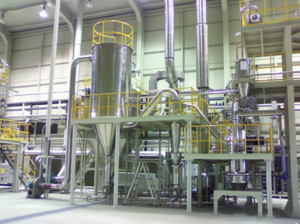
In a jet mill, compressed inert gas (nitrogen or dry air) is fed through nozzles into the milling chamber at high velocity. It’s typically 300-600 m/s at the nozzle exit, depending on gas pressure. The high-velocity gas streams entrain particles from the feed and accelerate them. Where two or more gas jets converge, the particles collide with each other at high relative velocity. These particle-on-particle collisions fracture the feed material through impact.
This is the critical difference from mechanical grinding: there are no grinding surfaces in contact with the product. The particles grind themselves. The only solid surfaces in the milling chamber are the chamber walls and the classifier wheel — both of which can be lined with ceramic or inert polymer materials to eliminate even those contamination pathways.
Why This Matters for Battery Cathode Chemistry
Cathode materials are chemically active. NMC, LFP, and LCO all contain transition metals that are sensitive to contamination from extraneous Fe, Cr, Ni, or Cu at the ppm level. They are also sensitive to moisture — particularly high-nickel NMC (NMC 811 and above). It reacts with atmospheric moisture to form surface lithium carbonate (Li2CO3) and lithium hydroxide (LiOH) species that degrade first-cycle efficiency and rate capability.
Jet milling in a closed nitrogen circuit addresses both concerns simultaneously: the absence of metal contact surfaces eliminates the primary contamination pathway, and the nitrogen atmosphere prevents moisture exposure throughout the milling cycle. This is why jet milling is the technology of choice for NMC 811 and other high-nickel cathodes that cannot tolerate either contamination type.
Jet Mill vs. Other Grinding Methods for Cathodes
| Property | Jet Mill | Ball Mill (ceramic) | Air Classifier Mill | Impact Mill |
| Metal contamination risk | Near zero | Low (ceramic wear) | Low-medium | Medium |
| Heat generation | None | Low-medium | Low | Medium |
| Inert atmosphere possible? | Yes (standard) | Yes (purged) | Limited | Limited |
| Finest achievable D50 | 0.5-1 micron | 1-3 microns | 3-5 microns | 5-10 microns |
| PSD sharpness (cut point control) | Excellent | Good | Excellent | Moderate |
| Energy cost per tonne | High (compressed gas) | Low-medium | Medium | Low |
| Throughput scalability | Medium-high | High | High | High |
Jet milling’s higher energy cost per tonne is justified for cathode applications where contamination and atmospheric sensitivity make other grinding methods impractical or require extensive protective measures that negate their cost advantage.
Choosing the Right Jet Mill Type for Your Cathode Material
Jet mills are not all the same design. For cathode material processing, two types are most commonly used: the fluidised bed jet mill and the spiral jet mill. They share the particle-on-particle grinding principle but differ in how they achieve size classification — and this difference determines which applications each type suits best.
Fluidised Bed Jet Mill
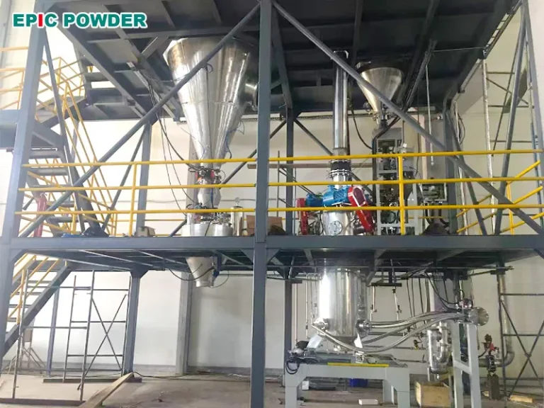
In a fluidised bed jet mill, gas jets enter horizontally through nozzles positioned around the lower chamber and create a turbulent, fluidised particle bed. Particles accelerate toward the centre where the jets converge, collide, and fracture. Milled particles are carried upward by the gas flow to an integrated dynamic classifier wheel at the top of the chamber. The classifier wheel speed controls the cut point: particles below the target size pass through the wheel to the product collection system; oversized particles are returned to the fluidised bed for further grinding.
- Strengths: adjustable cut point (D50 from 1 to 50+ microns), sharp PSD (tight span), high throughput at 5-100+ kg/h depending on mill size, suitable for temperature-sensitive and moisture-sensitive materials in closed nitrogen loop
- Best for: NMC cathodes, LFP, LNMO, and other cathode chemistries where a specific D50 and tight D97 are required and throughput is a production priority
- Limitation: higher capital cost than spiral jet mills; classifier wheel requires maintenance
Spiral (Pancake) Jet Mill
In a spiral jet mill, feed material and high-velocity gas enter tangentially into a flat, disc-shaped grinding chamber. The gas-particle stream follows a spiral path toward the centre of the disc, with particles accelerating as they converge. Size classification is achieved by the centrifugal force in the spiral flow — finer particles migrate to the centre and exit through the central outlet, while coarser particles remain in the outer spiral for continued grinding.
- Strengths: simple design, no moving parts (no classifier wheel), easy to clean and change products, compact footprint, lower initial cost
- Best for: R&D and pilot-scale work, small-batch processing of multiple materials, applications where quick product changeover and ease of cleaning are priorities
- Limitation: classification is self-regulating rather than adjustable — cut point is determined by gas pressure and feed rate, not a settable parameter. PSD is broader than fluidised bed mills at equivalent conditions. Not suitable for D50 targets below approximately 5 microns.
| Quick Selection Guide: Fluidised Bed vs. Spiral Jet Mill for Cathode Materials Use fluidised bed: when D50 below 10 microns is required, when tight D97 control is specified, when throughput above 20 kg/h is needed, or when the material is a high-nickel NMC with strict inert gas requirements Use spiral jet mill: for R&D and process development, for small production batches below 20 kg/h, when multiple products are run on the same equipment and quick cleaning is essential, or when budget limits capital investment Both types: can operate in closed nitrogen loop for moisture-sensitive cathodes — confirm this with the equipment supplier at the time of specification |
Key Operating Parameters and What They Control
Jet milling has four primary control variables. Understanding what each one does — and the interaction between them — is essential for setting up a stable, repeatable process recipe for your cathode material.
| Parameter | Typical Range (Fluidised Bed) | Effect on PSD | Notes |
| Grinding gas pressure | 4-8 bar | Higher pressure = finer D50. Below 4 bar: insufficient particle velocity for efficient grinding. | Primary energy input variable. Increasing pressure raises compressed gas consumption significantly. |
| Classifier wheel speed | 1,000-8,000 rpm (application-dependent) | Higher speed = finer cut point. Primary D50 control variable. | Most direct PSD control. Adjust in 200-500 rpm steps and sample after each change. |
| Feed rate | 5-60 kg/h (mill-size dependent) | Higher feed rate = slightly coarser product due to increased particle loading in classification zone. | Set at validated level. Inconsistent feed rate causes PSD variation. Use a controlled vibratory or screw feeder. |
| Nitrogen flow rate and purity | Matched to mill size; typically >99.9% N2 purity | Affects classification zone atmosphere; insufficient N2 purity allows moisture ingress. | For NMC 811+, N2 purity below 99.5% can cause measurable surface hydroxide formation. Monitor inline. |
The standard optimisation procedure is to set grinding pressure first (establish the energy input level appropriate for your material hardness), then adjust classifier wheel speed to hit the target D50, then fine-tune feed rate for throughput. Changes to any one parameter affect the others — always measure product PSD after each change and allow 5-10 minutes of steady-state operation before sampling.
Production Results: Three Cathode Material Applications
CASE STUDY 1
NMC 811 Cathode — Achieving D50 7 Microns in Closed N2 Loop
The requirement
A high-nickel NMC 811 cathode producer needed to achieve D50 7 microns with D99 below 28 microns for a high-energy automotive cell application. The material is highly moisture-sensitive — exposure to atmospheric humidity above 100 ppm H2O during milling causes measurable Li2CO3 formation on particle surfaces, which reduces first-cycle Coulombic efficiency. Their existing air classifier mill was producing D50 9-11 microns with D99 above 40 microns and required separate drying steps before and after milling to manage moisture uptake.
The solution
EPIC Powder Machinery supplied a fluidised bed jet mill with a closed nitrogen loop. Nitrogen purity was maintained at 99.9% (H2O below 20 ppm) throughout the milling cycle. The classifier wheel speed was set at 4,200 rpm and grinding pressure at 6 bar. Feed rate was established at 18 kg/h for the target fineness.
Results
Product PSD: D50 7.1 microns, D99 26 microns — within specification every production batch
Surface Li2CO3: measured by titration at 0.12% — within the cell manufacturer’s 0.15% maximum specification (vs. 0.31% on the previous air classifier mill process)
Separate drying steps: eliminated — moisture management handled entirely by the closed N2 loop
Throughput: 18 kg/h stable across 8-hour production runs
CASE STUDY 2
LFP Cathode — Scaling from Pilot to Production While Holding D50 3.5 Microns
The requirement
A lithium iron phosphate producer was processing LFP for energy storage applications at pilot scale (5 kg/h on a spiral jet mill, D50 3.8 microns) and needed to scale to 50 kg/h for production without changing the product PSD. Scaling a spiral jet mill by 10x is not straightforward — the self-regulating classification principle means PSD changes non-linearly with scale. They needed to switch to a fluidised bed jet mill at production scale and confirm that the PSD target could be replicated.
The solution
EPIC Powder Machinery conducted scale-up trials on a production-scale fluidised bed jet mill at our test facility, using the customer’s LFP feed material. The classifier wheel speed and grinding pressure were optimised to match the pilot-scale product PSD. The customer’s QA team attended and collected samples for independent laser diffraction and electrochemical analysis.
Results
D50 at 50 kg/h: 3.6 microns — within 5% of pilot specification
D99 at 50 kg/h: 14 microns — tighter than the pilot-scale spiral jet mill result of 18 microns (better classifier control on the fluidised bed design)
Throughput: 50 kg/h stable — 10x pilot scale
Electrochemical performance: rate capability (1C discharge capacity) equivalent to pilot-scale product, confirmed by customer’s cell testing
Equipment order: placed within 3 weeks of trial completion
CASE STUDY 3
LNMO High-Voltage Cathode — Pilot Trial for Next-Generation Cell
The requirement
A battery research institute was developing lithium nickel manganese oxide (LNMO) cathode material for a 5V-class high-voltage cell. LNMO is mechanically harder than NMC or LFP and has a specific requirement: grinding must not cause amorphisation of the spinel crystal structure, which would reduce the material’s 4.7V voltage plateau and degrade rate capability. Previous trials on a pin mill had produced D50 8 microns but with measurable XRD peak broadening indicating surface amorphisation from the mechanical impact.
The solutionA fluidised bed jet mill trial was conducted at EPIC Powder’s facility in closed nitrogen. Particle-on-particle grinding in the jet mill is gentler than pin mill impact in terms of crystal structure damage — the energy per collision is lower and distributed over a larger contact area. Grinding pressure was set conservatively at 5 bar with classifier wheel at 5,500 rpm to achieve D50 8 microns.
Results
D50: 8.2 microns — matching the pin mill target
XRD peak broadening: not detectable — spinel crystal structure fully preserved vs. measurable broadening on pin mill samples
4.7V plateau capacity: equivalent to unground reference material in half-cell testing
Conclusion: jet milling confirmed as the production process for LNMO cathode; pilot equipment order followed
Setting Up a Jet Milling Process for Cathode Materials: Practical Steps
Step 1: Define Your PSD Specification Before Selecting the Mill
Before specifying equipment, confirm your D50, D97, and Dmax targets with your cell manufacturer or internal electrode design team. These numbers drive mill type selection (spiral vs. fluidised bed), operating parameter range, and whether inert gas operation is required. Specifying only D50 is insufficient — D97 and Dmax control killer particle risk and electrode coating uniformity.
Step 2: Run a Test Grind on Your Feed Material
Cathode materials vary significantly in hardness, particle morphology, and grinding behaviour even within the same chemistry. NMC 811 synthesised by co-precipitation grinds differently from NMC 622 or NMC 523 at the same gas pressure. LFP from different synthesis routes (hydrothermal vs. solid-state) has different feed PSD and different grinding resistance. A test grind on your actual feed material — not a generic substitute — is the only reliable way to establish the operating parameters and throughput you will achieve at production scale.
Step 3: Establish and Document Your Process Recipe
Once the test grind confirms your parameters, document them as a fixed process recipe: grinding pressure, classifier wheel speed, feed rate, nitrogen purity threshold, and maximum allowable operating temperature. Set these as process limits in your control system. Jet mill performance is highly reproducible when parameters are held constant — batch-to-batch PSD variation is typically below 5% on D50 for a well-controlled process.
Step 4: Validate with Electrochemical Testing, Not Just PSD
PSD analysis confirms that the particle size target has been met, but it does not confirm that the milling process has not damaged the cathode material in other ways. For NMC and LFP, validate with at minimum: ICP-MS for metal contamination (total Fe, Cr, Ni, Cu), surface carbonate content (for NMC, by titration), BET surface area, and a half-cell electrochemical test (first-cycle efficiency, 0.1C and 1C capacity). Only when all four tests pass against your reference specification does the jet milling process have a validated baseline.
| Discuss Your Cathode Material Jet Milling Requirements with EPIC Powder Machinery Whether you are processing NMC 811, LFP, LNMO, or a next-generation cathode chemistry, EPIC Powder Machinery can configure a fluidised bed or spiral jet mill for your specific D50 target, inert gas requirement, and throughput. We offer free test grinds on your feed material — you get PSD data, contamination analysis, and a mill configuration recommendation before you commit.Send us your material data sheet and target particle size specification and we will design the right process. Request a Free Test Grind: www.jet-mills.com/contact Explore Our Cathode Material Jet Mill Range: www.jet-mills.com |
Frequently Asked Questions
What is the typical D50 achievable by jet milling for NMC and LFP cathode materials?
For NMC cathodes, typical production D50 targets are 5-12 microns for standard automotive and consumer cell applications. The fluidised bed jet mill can achieve D50 values below 3 microns on NMC if required. However, this is uncommon in production because finer particles increase surface reactivity and can accelerate electrolyte decomposition during cycling. For LFP, targets are finer: D50 1-5 microns for standard grades and D50 0.5-2 microns for high-rate LFP. The finest achievable D50 on a fluidised bed jet mill is approximately 0.5-1 micron, depending on material hardness and gas pressure. Below 1 micron, energy consumption rises steeply and throughput drops significantly — wet milling is often more economical at these sizes. Spiral jet mills are limited to approximately D50 3-5 microns for most cathode chemistries.
Why use nitrogen instead of air for jet milling cathode materials?
Dry compressed air is suitable for cathode materials that are not moisture-sensitive. Standard LFP and LCO can be jet milled in air without significant degradation. Nitrogen is required for high-nickel NMC (NMC 622 and above) for two reasons. First, moisture: NMC 811 and similar high-nickel compositions react with H2O at the surface to form lithium hydroxide (LiOH) and lithium carbonate (Li2CO3). These surface species reduce first-cycle Coulombic efficiency and impede lithium-ion diffusion. Even the small amount of atmospheric moisture in compressed air at 30-60% relative humidity is sufficient to cause measurable surface carbonate formation during a 1-2 hour milling run. Second, oxidation: at the elevated temperatures possible in high-pressure grinding, some cathode compositions can undergo surface oxidation in the presence of oxygen that changes the near-surface stoichiometry. Nitrogen purity of 99.9% (H2O below 50 ppm) is the standard specification for NMC 811 jet milling.
Can jet milling process solid-state electrolyte materials as well as cathode powders?
Yes, with appropriate configuration. Oxide solid electrolytes — LLZO (Li7La3Zr2O12), LATP, and LGPS — are all processable by fluidised bed jet milling. These materials are harder than most cathode materials and require higher grinding pressure (6-8 bar) and finer classifier settings to achieve the D50 targets typically required (0.5-3 microns for solid-state electrolyte in thin-film architectures). The contamination sensitivity is also higher — solid electrolytes are ionic conductors, and even ppm-level metal contamination can create short-circuit pathways or alter the local ionic conductivity. Full ceramic contact surfaces (no metal anywhere in the product path) and verified nitrogen purity above 99.9% are the standard requirements for LLZO and similar materials. Contact our engineering team for specific configuration recommendations for your solid electrolyte chemistry.
Epic Powder
Epic Powder, 20+ years of experience in the ultrafine powder industry. Actively promote the future development of ultra-fine powder, focusing on crushing, grinding, classifying and modification process of ultra-fine powder. Contact us for a free consultation and customized solutions! Our expert team is dedicated to providing high-quality products and services to maximize the value of your powder processing. Epic Powder—Your Trusted Powder Processing Expert!

“Thanks for reading. I hope my article helps. Please leave a comment down below. You may also contact EPIC Powder online customer representative Zelda for any further inquiries.”
— Jason Wang, Engineer